
Connecting to Your CNC Machine⁚ A Comprehensive Guide
This guide provides a comprehensive overview of connecting to your CNC machine. We cover various aspects, from understanding manual control and different connection manuals to advanced techniques and troubleshooting common issues. Safety precautions and software configuration are also discussed.
Understanding CNC Manual Control
Manual control of a CNC machine allows for direct, hands-on operation, bypassing the typical G-code programming. This is crucial for tasks like initial setup, precise adjustments, or troubleshooting. Many CNC machines offer a manual mode, often activated via a switch or software setting. In manual mode, you directly control the movement of each axis using handwheels, joysticks, or buttons. This enables precise positioning for tasks such as tool changes, workpiece alignment, or probing. The speed and direction of movement are typically controlled by adjusting knobs or using a digital interface.
Safety is paramount during manual control. Always ensure the machine is properly grounded and that emergency stops are readily accessible. Pay close attention to the machine’s movements, avoiding accidental collisions or unexpected actions. Some systems might allow for manual control only when power to the motors is disconnected, preventing unintended movement. Familiarize yourself with your specific machine’s manual control features and safety protocols before attempting any operation. Consult the machine’s documentation for detailed instructions and safety guidelines.
Types of CNC Connection Manuals
CNC connection manuals vary significantly depending on the machine’s manufacturer and control system. Fanuc, Yasnac, and Mitsubishi are prominent examples, each with its own documentation style and specific connection procedures. These manuals typically detail electrical and mechanical connections, providing wiring diagrams, pinouts, and interface specifications. They often include safety precautions, troubleshooting guides, and configuration instructions. The level of detail can range from basic connection diagrams to extensive technical specifications, addressing various aspects of the machine’s electrical and mechanical interfaces.
Beyond manufacturer-specific manuals, you’ll find manuals for specific control systems like Mach4. These cover software setup, communication protocols, and hardware integration. Some manuals focus on connecting specific peripherals, such as rotary encoders or external sensors. Others address networking configurations for remote control or data acquisition. The availability of online resources, such as manufacturer websites and online forums, can supplement these manuals, offering additional information and user experiences. Always ensure you are using the correct manual for your specific machine and control system, as incorrect connections can damage equipment or pose safety risks.
Fanuc Connection Manuals⁚ A Deep Dive
Fanuc CNC connection manuals are renowned for their comprehensive nature, often including detailed schematics, wiring diagrams, and precise specifications. These manuals typically cover various Fanuc control series, each with its own set of connection procedures and considerations. They often begin with safety warnings, emphasizing the importance of proper grounding and adherence to electrical safety regulations. The manuals then detail the physical connections, often using labeled diagrams and tables to identify specific pins and their functions. This ensures correct interfacing with the machine’s various components, including motors, sensors, and external devices.
Fanuc manuals often include sections dedicated to troubleshooting common connection issues, providing step-by-step guidance on diagnosing and resolving problems. They may also describe different communication protocols, such as serial communication, and provide settings for baud rate, parity, and other parameters. Furthermore, Fanuc manuals often cover the integration of additional peripherals, offering detailed instructions on connecting and configuring external equipment. The depth and detail of these manuals make them essential for technicians and engineers working with Fanuc CNC machines. Always consult the most up-to-date version of the manual specific to your Fanuc control model to ensure safe and successful connections.
Yasnac Connection Manuals⁚ Key Features
Yasnac connection manuals, while varying slightly depending on the specific CNC model, generally prioritize clarity and ease of understanding. Unlike some manuals dense with technical jargon, Yasnac documentation often employs a more accessible approach, making them user-friendly even for those with limited experience in CNC technology. A key feature is the inclusion of comprehensive wiring diagrams, meticulously detailing each connection point and its corresponding function within the system. These diagrams are usually well-organized and clearly labeled, minimizing the risk of misconnections.
Yasnac manuals typically include detailed specifications for various machine interfaces and external equipment. They often describe the necessary connections that must be provided by the machine builder, highlighting the importance of correct installation for optimal performance and safety. Furthermore, the manuals often incorporate troubleshooting sections, offering practical guidance on resolving common connection problems. These sections may include checklists, flowcharts, or step-by-step instructions, aiding in quick and efficient problem diagnosis. Detailed safety precautions are also a prominent feature, ensuring users understand potential hazards and take the necessary steps to prevent accidents or damage to the equipment. The focus on practical guidance and user-friendliness sets Yasnac connection manuals apart.
Mitsubishi CNC Connection Manuals⁚ Setup and Installation
Mitsubishi CNC connection manuals provide detailed instructions for setting up and installing their control systems. These manuals typically begin with an overview of safety precautions, emphasizing the importance of grounding and proper electrical connections to prevent hazards. Next, they guide users through the physical installation process, providing clear diagrams and instructions for connecting the CNC unit to the machine tool. This often involves connecting various components such as motors, encoders, and input/output devices. The manuals meticulously detail the specific wiring requirements for each component, including pin assignments and cable types.
A crucial section of these manuals addresses the software setup. Mitsubishi manuals usually explain how to configure the CNC control parameters to match the specific machine tool’s characteristics. This includes settings related to motor control, axis limits, and tooling information. Detailed steps are provided to ensure correct communication between the CNC and the connected devices. Troubleshooting sections often address common issues encountered during setup and installation, offering solutions and workarounds for various problems. The manuals aim to equip users with the knowledge and resources to successfully install and configure their Mitsubishi CNC systems, emphasizing a step-by-step approach for a smooth installation process.
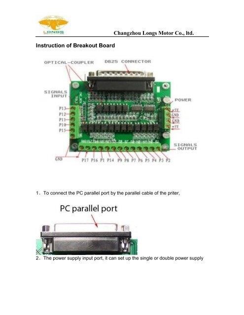
Troubleshooting Common Connection Issues
Troubleshooting CNC connections often involves systematically checking various aspects of the setup. Loose or incorrectly wired connections are a frequent culprit; carefully inspect all cables and terminals, ensuring secure and correct connections. Refer to the specific CNC machine’s manual for wiring diagrams and pinouts. Incorrect serial port settings (baud rate, parity, data bits, stop bits) can prevent communication; verify these settings match between the CNC controller and the computer. If using a software interface, ensure the correct communication protocol (e.g., RS-232, Ethernet) is selected and configured properly. Check for any error messages displayed on the CNC controller or the computer software; these messages often pinpoint the problem’s source.
Power supply issues can also disrupt communication; confirm the CNC controller is receiving sufficient and stable power. Faulty cables or connectors can cause intermittent or complete communication failures; try replacing suspect cables or connectors with known good ones to isolate the issue. Grounding problems may lead to erratic behavior or electrical hazards. Ensure proper grounding according to the manufacturer’s instructions. If the problem persists after these checks, consult the CNC machine’s manual for advanced troubleshooting steps or contact the manufacturer’s technical support for assistance. Documenting each step and observation during troubleshooting helps identify the root cause and facilitates future repairs.
Configuring Software Settings for CNC Control
Configuring software settings for CNC control is crucial for proper operation and communication. Begin by installing the appropriate software for your CNC machine and controller type. Consult the manufacturer’s documentation for specific installation instructions and compatibility details. After installation, access the software’s configuration settings. These settings typically include communication parameters such as the serial port, baud rate, parity, data bits, and stop bits. Ensure these settings match the CNC controller’s configuration to establish a reliable connection. The software may also require machine-specific settings, such as the number of axes, step size, and motor speeds. Incorrect settings can lead to inaccurate movements or control issues. Refer to your machine’s manual for these parameters.
Many software packages allow for custom tool definitions. Input the correct dimensions and characteristics of your tools, such as diameter, length, and cutting parameters. This information is crucial for accurate toolpath calculations. Calibration is essential for precise control. Follow the software’s instructions for calibrating each axis of your CNC machine. This typically involves moving each axis a known distance and verifying the software’s measurement. Regularly check and adjust these settings as needed, especially after significant changes to your machine or tooling. Maintaining accurate software configurations is vital for producing high-quality and consistent results in CNC machining.
Connecting Rotary Encoders for Manual Control
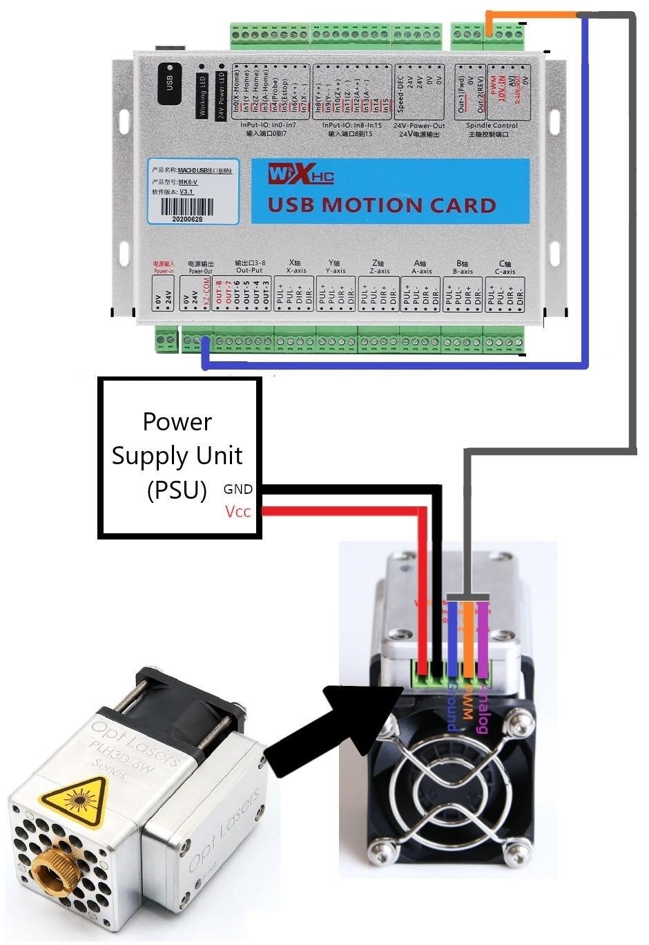
Connecting rotary encoders to your CNC machine enables manual control, providing a more hands-on approach to precise positioning. This setup allows for fine adjustments and direct manipulation of the machine’s axes, especially useful during setup or intricate machining tasks. Before connecting, ensure compatibility between your encoders and the CNC controller. Refer to both the encoder and controller manuals for specific wiring diagrams and connection instructions. Typically, rotary encoders have three wires⁚ two for signal output (A and B channels) and one for ground. Incorrect wiring can damage components, so carefully follow the provided diagrams.
The signal outputs from the encoders need to be connected to input ports on your CNC controller. These ports are specifically designed to receive pulses from encoders, which represent the rotational movement. The controller’s software needs to be configured to recognize and interpret the signals from the connected encoders. This involves setting parameters like the number of pulses per revolution, direction of rotation, and scaling factors to ensure accurate position feedback. After connecting the encoders and configuring the software, test the system thoroughly. Carefully move the handwheels connected to the encoders and observe the corresponding movement of the machine axes on the controller display. Verify the accuracy of the positioning by measuring the actual movement and comparing it to the indicated values.
Different Control Systems⁚ Mach4, Others
The CNC control system dictates how you connect and interact with your machine. Popular options include Mach4, LinuxCNC, and proprietary systems from manufacturers like Fanuc, Siemens, and Yaskawa. Each system boasts unique features and connection methods. Mach4, a widely adopted software-based controller, offers user-friendly interfaces and extensive customization options. Its connection process typically involves configuring communication parameters (baud rate, parity, etc.) to match your machine’s interface, often using serial or parallel ports. Detailed instructions are usually found within the Mach4 documentation, specific to the chosen hardware.
Other systems like LinuxCNC, an open-source solution, provide flexibility and community support. Connecting LinuxCNC involves configuring the system’s configuration files, specifying the type of hardware interface (parallel port, Ethernet, etc.), and setting up the communication parameters. Proprietary systems supplied by CNC machine manufacturers usually come with their own comprehensive manuals. These manuals detail the connection process, including pinouts, wiring diagrams, and software configuration steps. Understanding your specific control system is crucial for successful connection. Always consult the relevant manuals for your chosen system, ensuring compatibility between the controller and your machine’s hardware. Improper configuration can lead to malfunctions, data loss, or even machine damage.
Importance of Grounding and Safety Precautions
Before connecting your CNC machine, prioritize safety. Proper grounding is paramount to prevent electrical shocks and equipment damage. Grounding provides a low-resistance path for stray electrical currents, diverting them safely to the earth. Failure to ground your CNC machine properly can lead to serious injury or even death. Always ensure your CNC machine is connected to a properly installed and grounded electrical outlet. Never bypass safety features or attempt repairs without proper training and knowledge.
Consult your machine’s manual for specific grounding instructions. These instructions often specify the type of grounding connection required (e.g., three-prong plug, dedicated grounding wire), the appropriate grounding point on the machine, and the impedance requirements. In addition to grounding, always follow the safety guidelines provided in your machine’s manual. These guidelines cover various aspects, including emergency stop procedures, machine guarding, proper personal protective equipment (PPE) use, and safe operating practices. Never operate the CNC machine without a thorough understanding of its safety features and operating procedures. Regularly inspect your machine for any signs of wear or damage that could compromise safety. Addressing any safety concerns promptly is vital for minimizing risks.
Serial Port Configuration and Settings
Establishing communication between your computer and CNC machine often involves configuring the serial port. This typically includes specifying the communication parameters such as baud rate, data bits, parity, and stop bits. These settings must match on both the computer and the CNC controller to ensure successful data transmission. Incorrect settings will result in communication errors or complete failure to connect. Consult your CNC machine’s manual for the correct serial port settings. These settings are often device-specific and vary among different CNC controllers and software applications.
Many CNC machines utilize RS-232 serial communication, a standard interface for connecting devices. However, some newer machines may use other protocols like Ethernet or USB. If using RS-232, you’ll need a serial port on your computer or a USB-to-serial adapter. Within your computer’s operating system, you’ll need to configure the serial port settings to match those specified in your CNC machine’s documentation. This typically involves selecting the correct COM port, baud rate (e.g., 9600, 19200, 115200), data bits (usually 8), parity (often None), and stop bits (usually 1). Once these parameters are correctly set, you can then proceed with establishing a connection between your computer and CNC machine using appropriate software.
Understanding CNC Machine Interfaces
CNC machines employ various interfaces to facilitate communication with external devices like computers and other peripherals. Understanding these interfaces is crucial for successful connection and control; Common interfaces include serial ports (RS-232, often used for older machines and simple connections), parallel ports (less common now, offering higher data transfer rates but limited distance), and Ethernet (providing high-speed communication over a network, ideal for modern CNC machines and advanced control systems). USB interfaces are also frequently used for simpler connections and data transfer, although their suitability for real-time control can vary.
The specific interface used depends heavily on the CNC machine’s manufacturer and model. Older models might only have serial ports, while newer ones often incorporate Ethernet for advanced networking capabilities. Some machines may even offer multiple interface options, allowing flexibility in connection methods. Before attempting any connection, always consult the machine’s manual to identify the available interfaces and their specific configurations. This will include details such as connector types, pinouts (for serial and parallel ports), and network settings (for Ethernet). Correct identification and understanding of the CNC machine’s interfaces are essential for establishing a reliable and functional connection with external control systems.
Advanced CNC Connection Techniques
Beyond basic serial or Ethernet connections, advanced techniques enhance CNC machine control and integration. These include implementing DNC (Direct Numerical Control) systems, which allow for direct communication between a central computer and multiple CNC machines, enabling efficient job scheduling and data transfer. This eliminates the need for manual file transfer to each machine, improving productivity. Another sophisticated technique involves using industrial fieldbuses like Profibus or Profinet, which provide real-time data exchange and precise control over multiple devices in a manufacturing environment. This is particularly useful in complex automated systems.
Advanced techniques also include integrating CNC machines with PLCs (Programmable Logic Controllers) for automated sequences and process control. PLCs can monitor sensor inputs, trigger CNC actions, and handle complex production workflows. Furthermore, sophisticated software solutions offer remote monitoring and control of CNC machines via the internet, enabling remote diagnostics, maintenance, and even operation. Such advanced connections often require specialized knowledge of networking protocols, industrial communication standards, and programming skills. These advanced methods require a detailed understanding of the specific CNC machine’s capabilities and communication protocols, as well as the software and hardware involved in the control system. Proper implementation can significantly improve efficiency, automation, and remote monitoring capabilities.